![]()
Opto isolated 1-Wire bus ( (c) Dallas semiconductors )
When building a 1-Wire MicroLAN, you can run into some difficulties in the way of safety
and realibilty. Reason is that the whole network has a galvanic coupling.
Where could you think of:
- Controlling mains applications; motors / valves / lights.
- ESD of touching ibuttons
- Ground loops
- Lightning
- PC / ethernet coupling
The most usefull way is to isolate the 1-Wire databus directly.

Figure 1 Block schematic of the 1-Wire isolater
I designed the following features in the circuit:
Features
Schematic
![]()
Figure 2 Schematic for the optical 1-Wire coupler
Short circuit-description:
When 1-Wire IN is high no current is flowing through the led
of ISO1, the ISO1-output is high,
T3 is not driven and so the 1-Wire OUT is also high.
When 1-Wire IN is low current is flowing through ISO1 led and the output
of it is low, T3 is driven
and the 1-Wire OUT is also low.
The difficult part: When a slave at the 1-Wire OUT sends back a zero, current is
flowing through
R18, resulting in a high of pin 14 of IC1. Pin 13 is driving the led of ISO2 and
the output of it is low,
resulting in a low at the input. When the slave stops to send a zero, the led is
not been driven anymore
and the 1-Wire input will be released.
Current is only detected when the output is low ( not when
temperature-sensors are converting temps )
so the current -sensing circuit is only working with slave-zero-readback.
Smart pullup: 60uS after a rising edge, T2 starts conducting the
drive more power at the output.
When no parasitic power is needed the circuit can be made a little bit simpler,
see figure 3.
IC2 is an isolated power supply. When there is power at the slave side, this
power supply is not
needed.
![]()
Figure 3 Schematic without "Smart pullup"
Some pictures of the prototype
Click on the pictures to enlarge.
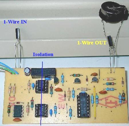

Optocouplers Use of a fibre
Some oscilloscope signal traces
I did some measurements on my prototype, to check the correct function of it
and to analyse
the shapes of the 1-wire signals. Also the delaytimes can be checked.
Scope 1:
In the scope 1 traces you see the repeater-function. The uppertrace is a 150 metres
loaded network.
The lower signal is the output of the coupler. All the edges are fresh again and
able to drive a long network.
Scope 2:
In these traces you see a funny use of the coupler: No input load and a heavy
outputload.
The inputtrace is clean and sees no load at all! The output trace shows a loaded
1-wire bus.
Due to limited slew-rates and speed of components there's some delay between
the input
and output of the circuit. The reaction delaytime on the falling edge is an
important one!
In the traces below the reaction / delay time is shown. The delaytime is within
the specs of the
1-wire protocol.
Due to these delays you may use only one coupler in a master / slave network.
Idea to make a lightning barrier
When a fibre is used as coupler a perfect barrier can be made.
You needed an 1-wire to opto transmitter; 2 x single plastic fibre; opto to
1-wire receiver.
Both transmitter and receiver need a supply voltage. The receiver can be
supplied by
4 times NiMH / NiCD accu's and and a solarcell ( for charging the accu's ).
A block-diagram is shown below;
Project status
The project is still in the prototype fase, but is working very well in different
configurations.
We are now doing an engineering cycle, to make the circuit simpler. It's now
containing
2 opto-couplers, 1 IC, a DC/DC-converter and a handfull of other
components.
We also do some more tests with the fibers and some common ( audio ) fiber transmitters / receivers.
June 2007: I build succesfully a Fibre circuit using
the Toshiba audio fiber transmitters / receivers TOTX173 / TORX173.
Click below to see the schematic. To save some money, the TOTX173 can be
replaced by a transistor and a Red led.
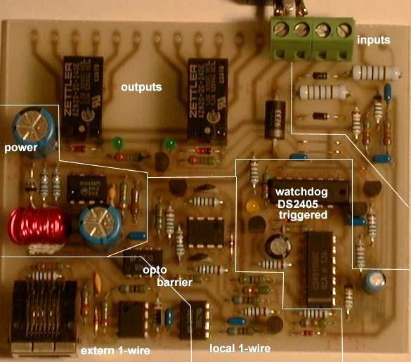
Fig. A Working example isolated 1-wire mainscontrolunit
Reaction at: ![]()